LINEAR TRACK GUIDANCE
- INSTALLATION
For optimum performance, the track guidance system should be set up following these guidelines.
A. Mounting
1. Make sure the surface on which the track is to be laid is flat
2. Handle all items with care and make sure hand and finger marks are wiped over with WD40 or similar to prevent rusting on bright steel surfaces.
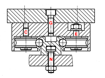
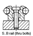
3. Bolts to be tightened to following torques in Nm. See drawing above for component.
| Carriage Component |
Guideway Component |
Size 25 | Size 36 | Size 54 |
|---|---|---|---|---|
| Thread (G) | - | 5.5 | 23 | 46 |
| Eccentric Bolt (E) | - | 2.4 | 8 | 40 |
| Concentric Bolt (C) | - | 2.4 | 8 | 40 |
| - | Fixing Bolt (N) | 6 | 10 | 46 |
4. If using two guideways make sure they are parallel by careful measurement.
5. If side thrust is expected make sure that the carriage is installed so that the load is acting on the CONCENTRIC bolts of the track rollers.
Catalogue
Correctly assembled, the assembly is set clearance free by means of adjusting the eccentric bolts and then locked into position by lock nut E (see above drawing). The carriage should then be movable by applying a light force, ensuring all rollers are rotating in contact with the guideways.
Excessive preloads are not necessary and reduce the life of the system.
Carriage references LW..-4.. have a lubricating/wiper elements which contact the guideways to keep them lightly oiled. Lubricate through the nipples which feed the oil reservoir using a slideway oil. This must be done prior to using the system and at regular intervals.
The track roller bearings are sealed for life and require no lubrication.
Related Products and Links