MOTION GUIDANCE SYSTEMS - TECHNICAL INFORMATION
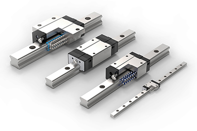
TW guide rails offer quiet, smooth running together with high precison. Typical applications include CNC machines, machine tools, cutting machines, precision measuring machines, packing machines, welding machines and material handling.
With 8 different carriage designs and a range of sizes from 15 to 55, we can offer an alternative to almost all profiled linear rail guides on the market.
Advantages and Features
- Competitively priced and short lead times
- Rails are available in sizes 15 to 55
- 8 different styles of carriage blocks
- Option to fix the carriages from above or below
- Quiet and smooth running
- X arrangement of the balls helps to compensate for inaccuracies of mounting surface
- Balls are retained if the carriage is removed from the profile rail
- Sealed carriage with various wiper and lubrication options
Speed. vmax = 2 to 3 m/s *
Temperature range -10ºC to +80ºC
*The maximum obtainable speed depends on the carriage model, configuration and loads
Calculation of service life
The service life is defined as the distance that can be traveled before the raceway or rolling elements begin to flake.
Service life can be reduced due to a number of factors including:
- Contamination by foreign substance
- Insufficient lubrication
- Short stroke length or shock forces
- Overloading
- Damage to the plastic end retainers
Technical Definitions:
The dynamic load rating (C) is the constant load, in direction and magnitude, on a linear guide under which the nominal service life is 50km.
The static load rating (C0) ensures that the deformation of the rail due to a high impact load is no more than 0.0001 times bigger than the diameter of the ball. This is to ensure smooth running.
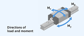
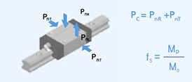
The allowable static moment (M0) limits the deformation of rail by ensuring the ball at the end (most loaded) does not cause a indentation in the rail greater than 0.0001 times the diameter of the ball. Moment loads in the three directioms (Mp, Mr and My) are listed for each type of carriage. The allowable static moment M0 and the static moment load rating Mp can be reviewed by applying a safety factor (fs).
[Calculation of service life]
Load Calculation:
The forces must be combined into an equivalent load (Pc) in order to calculate the service life. It is important to include drive forces and acceleration torques in this.
The nominal service life is calculated from the dynamic load C and the equivalent dynamic load Pc together with reduction factors listed below.
Where there are several carriages in a system, the service life should calculated based on the carriage subjected to the highest forces.
Formula for calculating the service life:
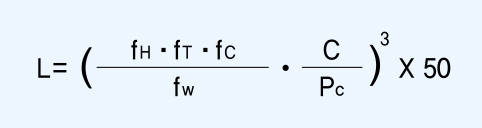
where:
L = Service Life (km)
C = Basic dynamic load rating (N)
Pc= Calculated load (N)
fH = Hardness factor*
fT = Temperature factor*
fc = Contact factor*
fW = Load factor*
Reduction Factors:
Load factor fW -
If the carriages are subjected to shock or vibration, then the loads seen by the carriages will be higher. Select the load factor from below:
No shock or vibration, fW = 1.0 to 1.5
Moderate shocks or vibrations, fW = 1.5 to 2.0
Moderate shocks or vibrations, fW = 2.0 to 3.0
Temperature factor fT -
The maximum continuous operating temperature is 80ºC. For this range of temperatures fT =1. When using special high temperature guides, the temperature factor is available on request.
Hardness factor fH -
Since the raceways are hardened, fH =1
Contact factor fC -
For a classic arrangement of two rails with four carriages, fc =1
If there is only one rail with two carriages fc =0.81
Or for one rail with three carriages fc =0.72
[Calculation of service life]
Lifetime Calculation:
If the length and frequency of the stroke is constant, then the lifetime can be calculated as follows:
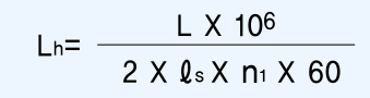
where Lh = Life time (hours)
ls = Length of stroke (mm)
and n1 = number of strokes per minute (mm-1)
ACCURACY
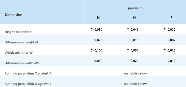
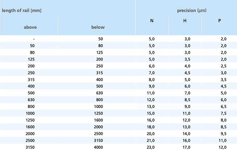
The accuracy is determined by the dimension tolerance (and deviation) along with the parallelism of the guide rails.
Dimension Tolerance (mm):
[Accuracy]
Parallelism (µm):
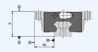
The parallelism stated in the table below is the deviation along the entire length of the rail both vertically (from the top of the carriage [C] relative to the base of the rail [A]) and also horizontally (from the side of the carriage [D] relative to the side of the rail [B]).
[Accuracy]
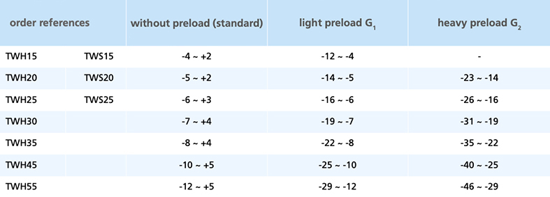
Preload (µm):
Preload of Linear Motion carriages TWH and TWS (in µm)
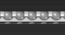
Spacer Chain Option (+S)
The carriages can be specified with a spacer chain by adding +S to the end of the part number. The spacer chain holds the balls to prevent them from colliding when they recirculate. The main benefit is a reduction in noise, but it also reduces the friction and enables higher running speeds. The ball chain provides additional pockets for the lubricant and hence it can be relubricated less frequently. A spacer chain should not be used if there is a lot of dirt.
SEALS and LUBRICATION
Seals and Scrapers
The carriages are supplied with SS seals by default. However other sealing arrangements are available as follows:
SS = end and inner seals
UU = end seals only
ZZ = end and inner seals, plus metal scraper
Please be aware that the scraper (ZZ) will make the overall carriage length longer.
Lubrication Unit (LF)
The lubrication unit is an optional extra. It can be supplied in conjunction with any seal option (SS, UU, ZZ). In many applications the lubrication unit will facilitate maintenance-free operation. The porous synthetic material contains lubricant which is continuously released during movement.
- Max operating temperature 40ºC
- Do not allow the lubrication unit to come into contact with solvents or cleaning agents.
The lubrication block typically adds around 15mm to the length of the carriage. The actual length can be provided on request.
Related Products and Links