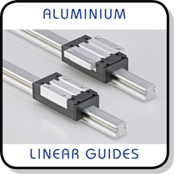
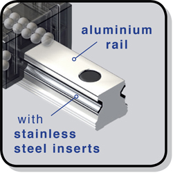
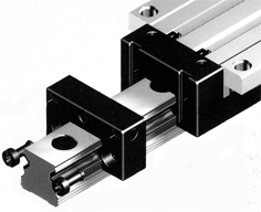
ALUMINIUM MOTION GUIDANCE
- RAILS (A and B)
A type rail is bolted from the TOP with the cap of the bolt countersunk into the rail. B type rail is bolted from the BOTTOM (with the cap of the bolt located in the structure to which the rail is bolted).
Available in lengths of up to 4000mm.
Use in conjunction with the GNS and FNS carriages.
Details of lubrication blocks are shown below.
Dimensions are in millimetres.
Catalogue
Rail Dimensions
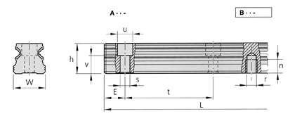
| Part Number | W | h | u | v | s | E | Emin | r | n | t | Lmax | Weight | 3D Cad |
|---|---|---|---|---|---|---|---|---|---|---|---|---|---|
| A15- | 15 | 14 | 7.5 | 8.1 | 4.4 | 28 | 10 | - | - | 60 | 4000 | 0.57 | |
| B15- | 15 | 14 | - | - | - | 28 | 10 | M5 | 7 | 60 | 4000 | 0.57 | |
| A20- | 20 | 19 | 9.5 | 11.6 | 6 | 28 | 10 | - | - | 60 | 4000 | 0.98 | |
| B20- | 20 | 19 | - | - | - | 28 | 10 | M6 | 9 | 60 | 4000 | 0.98 | |
| A25- | 25 | 21.8 | 11 | 12.9 | 7 | 28 | 10 | - | - | 60 | 4000 | 1.25 | |
| B25- | 25 | 21.8 | - | - | - | 28 | 10 | M6 | 12 | 60 | 4000 | 1.25 |
All dimensions are in mm. Weight is in kg/m.
Lubrication Blocks
Lube blocks are simply slid onto the guide rail and fastened to the carriage. They are supplied with straight grease nipples as standard but angled grease nipples can be fitted on request.
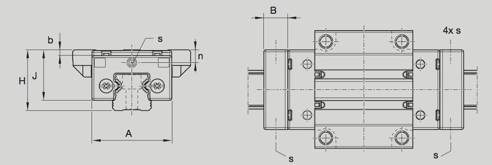
| Part Number | A | B | H | J | b | n | s | Oil (cm3) | Nipple |
|---|---|---|---|---|---|---|---|---|---|
| DSF-1500 | 32.2 | 11.5 | 24 | 19.4 | 0.4 | 4.5 | M3 | 0.65 | nSN-00M3 |
| DSF-2000 | 43.2 | 15.5 | 30 | 24.3 | 0.4 | 5 | M6 | 1.35 | nGN-00M6 |
| DSF-2500 | 47.2 | 16.4 | 36 | 30 | 0.4 | 7.4 | M6 | 1.7 | nGN-00M6 |
Related Products and Links