Combined Roller Bearings and Steel Profiles
The following article was published in The Engineer Magazine.
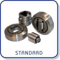
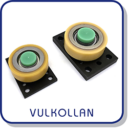
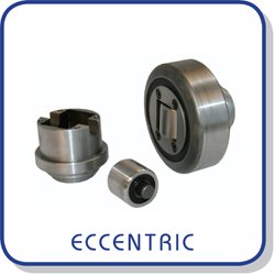
A combined roller bearing comprises a ‘maximum-capacity’ cylindrical roller bearing, full of steel rollers and without a cage to separate them. It is of a non-separable design that rotates on a weldable steel hub, which is known as a radial roller.
Inside the hub and set at 90º to the radial roller is another bearing (again of maximum capacity) needle roller. This is known as an axial roller.
Both bearings are sealed with hybrid rubber/metal seals.
These products have been used to carry loads from tens of kilos up to hundreds of tonnes.
To use a combined roller bearing, a hole the same size as the spigot on the rear of the hub is drilled or milled in a steel member. The hub is then welded into place, filling the 45º weld fillet around the circumference of the spigot with weld.
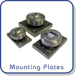
An optional mounting plate is available that allows the user to pre-weld the bearing to the plate and then attach the plate using bolt and nut through clearance holes or machine screws into the threaded holes in the plate.
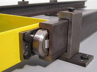
In use, the combined roller bearing engages in a C- or H-section profiled steel section. The radial roller engages on the flanges of the profiled section and the axial roller engages on the web of the profiled section. These sections are much thicker and heavier in section than ‘standard’ beams or columns. The profile is formed to exactly match the bearing’s outer profile.
When designing a heavy-duty sliding system, it is very unlikely that the radial bearing will crab or lock in its steel section because any twisting action is immediately counteracted by the axial bearing running into and along the web. As both bearings are cylindrical/needle roller types, they immediately want to rotate under dynamic load.
Forklift truck manufacturers are aware that, for many years, there has been a tendency within the mast for the bearings they were using to crab. This meant that the mast bearing would actually skid, crab or, in the worst cases, lock in the mast channel. To prevent this from happening, many fork-truck manufacturers would use a second ‘side load roller’ bearing.
The combined roller bearing simply brings this solution into one unit by combining the main load carrier (radial bearing) with the anti-twist bearing (axial bearing). The potential user can see that mounting and using this bearing is straightforward and ‘engineers out’ many operations required in mounting a bearing as a track roller.
Very few of the combined roller bearings and steel profiles find their way into fork trucks in the UK today; this is because there are very few companies actually making fork trucks in the UK.
Most combined roller bearings and steel profiles find their way into specialised handling equipment. An example of this is the special lift mechanism created to lift the 50-tonne wing of the A380. Massive jumbo bearings and special welded and profiled rails were used to achieve this.
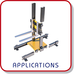
A production engineer can use four small combined bearings and two of the smallest steel profiles to create a low-cost slide to move a workpiece from one machine to the next.
Typical applications for these products include: oil drilling and exploration equipment; marine cable and pipe-laying equipment; palletisers; goods lifts; vehicle lifts; test rigs; materials-handling equipment; lighting gantries; furnace chargers/dischargers; manufactured concrete and aggregate conveyors; machine tool positioning; agricultural equipment; specialised vehicles trailers; CNC tool storage; theatre and film applications; brick making; medical equipment; fleet support; and fork-truck attachments.
En Français? Voir notre catalogue ici. 
Related Products and Links

