MOTION GUIDANCE SYSTEMS - TWS COMPACT Linear Guides
The TWS guide rails contains 4 rows of balls arranged in a circular arc design providing the balls with a 2-point contact.
Carriage Types:
The compact carriages are available for rail sizes 15 to 25 in the following four designs:
1) A compact block carriage (-CR) for bolting from above.
2) A compact flanged version (-CF) for bolting from above or below.
3) A long compact block carriage (-R) for bolting from above with greater load capacity.
4) A long compact flanged carriage (-F) for bolting from above or below with greater load capacity.
The guide rails are interchangeable between all the designs of carriages and are available with countersunk holes for bolting from above (TWO) or with threaded holes for bolting from underneath (TWU).
Features:
- Equal load capacity in all directions due to 45º contact angle of the raceways.
- The X arrangement of the ball rows compensates for inaccuracies of the mounting surface.
- High precision and free running due to 2-point contact of the balls in the raceways.
- Inner seal provides additional protection from contamination.
- Quiet and smooth running
- X arrangement of the balls helps to compensate for inaccuracies of mounting surface
- One design of rail for all types of carriages
Speed. vmax = 2 to 3 m/s *
Temperature range -10ºC to +80ºC
*The maximum obtainable speed depends on the carriage model, configuration and loads
TW LINEAR RAILS
TWO Standard Rail:
The TWO rail is standard type. It features countersunk holes for bolting from above. This rail can be used for all designs of TWH and TWS carriages.
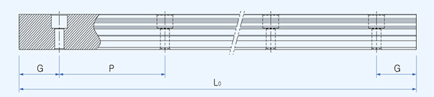
| Part Number | Pitch P | Hole S | h (mm) | Weight (kg/m) |
|---|---|---|---|---|
| TWO15 / TWU15 | 60 | M5 | 8 | 1.30 |
| TWO20 / TWU20 | 60 | M6 | 10 | 2.20 |
| TWO25 / TWU25 | 60 | M6 | 12 | 3.00 |
The maximum length of rail is 4000mm. The rails will be cut symmetrically (G=G) unless requested otherwise.
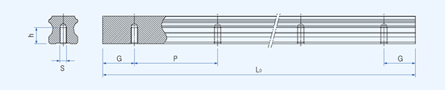
TWU Rail:
The TWU rail is designed for bolting from below. It features threaded holes and can be used for all designs of TWH and TWS carriages. It is available in 7 different sizes - from 15 to 55.
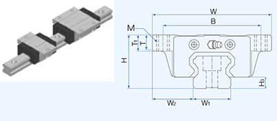
TWS Linear Carriages - BLOCK
Block Carriages TWS..CR and TWS..R
The TWS..CR and TWS..R compact linear carriages are designed for bolting from above. Use with either TWO or TWU linear rails. These compact carriages offer a lower overall height and the option of two bolt holes (TWS..CR) or four bolt holes (TWS..R). Technical information is available regarding preloads, service life and accuracy. Standard carriages (TWH) are also available.
| Part Number | H | W | L | B | C | Mxl | L1 | T | N | E | Grease | H3 |
|---|---|---|---|---|---|---|---|---|---|---|---|---|
| TWS15CR | 24 | 34 | 39.8 | 26 | - | M4x6 | 24.0 | 6 | 6 | 4.7 | A-M5 | 4.5 |
| TWS15R | 24 | 34 | 56.5 | 26 | 26 | M4x6 | 40.7 | 6 | 6 | 4.7 | A-M5 | 4.5 |
| TWS20CR | 28 | 42 | 47.8 | 32 | - | M5x7 | 27.6 | 7.5 | 5.5 | 10.7 | B-M6F | 6.0 |
| TWS20R | 28 | 42 | 66.8 | 32 | 32 | M5x7 | 46.7 | 7.5 | 5.5 | 10.7 | B-M6F | 6.0 |
| TWS25CR | 33 | 48 | 59.4 | 35 | - | M6x8 | 34.4 | 8 | 6 | 10.2 | B-M6F | 7.0 |
| TWS25R | 33 | 48 | 83.2 | 35 | 35 | M6x8 | 58.2 | 8 | 6 | 10.2 | B-M6F | 7.0 |
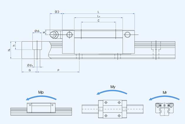
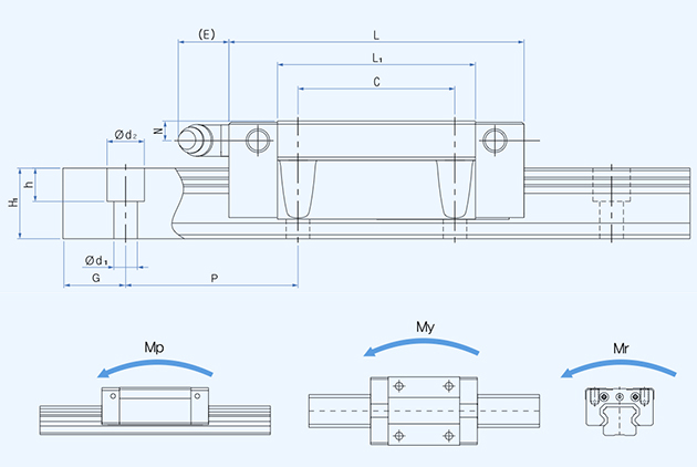
Loads and Moments for Block Carriages TWS..CR and TWS..R
| Part Number | W1 | W2 | H1 | P | d1xd2 xh | C (kN) |
C0 (kN) | Mp = My |
Mp2 = My2 |
Mr | Block (kg) |
|---|---|---|---|---|---|---|---|---|---|---|---|
| TWS15CR | 15 | 9.5 | 13.0 | 60 | 4.5x7.5x5.3 | 9.0 | 10.0 | 0.042 | 0.224 | 0.079 | 0.096 |
| TWS15R | 15 | 9.5 | 13.0 | 60 | 4.5x7.5x5.3 | 12.6 | 16.2 | 0.115 | 0.552 | 0.129 | 0.156 |
| TWS20CR | 20 | 11.0 | 16.5 | 60 | 6x9.5x8.5 | 12.0 | 13.1 | 0.063 | 0.342 | 0.137 | 0.153 |
| TWS20R | 20 | 11.0 | 16.5 | 60 | 6x9.5x8.5 | 16.8 | 21.2 | 0.173 | 0.838 | 0.223 | 0.246 |
| TWS25CR | 23 | 12.5 | 20.0 | 60 | 7x11x9 | 19.2 | 20.4 | 0.123 | 0.670 | 0.246 | 0.254 |
| TWS25R | 23 | 12.5 | 20.0 | 60 | 7x11x9 | 27.0 | 33.1 | 0.337 | 1.636 | 0.398 | 0.413 |
Moments are in kNm and dimensions are in mm. Mp2 and My2 are the moment capacities when two carriages are used in close contact.
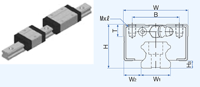
TWS Linear Carriages - FLANGED
Flanged Carriages TWS..CF and TWS..F
The TWS..CF and TWS..F compact linear carriages are designed for bolting from above or below. Use with either TWO or TWU linear rails. These compact carriages offer a lower overall height and the option of two bolt holes (TWS..CR) or four bolt holes (TWS..F). Technical information is available regarding preloads, service life and accuracy. Standard carriages (TWH) are also available.
| Part Number | H | W | L | B | C | M | L1 | T | N | E | Grease | H3 |
|---|---|---|---|---|---|---|---|---|---|---|---|---|
| TWS15CF | 24 | 52 | 39.8 | 41 | - | M5 | 24.0 | 6 | 6.0 | 4.7 | A-M5 | 4.5 |
| TWS15F | 24 | 52 | 56.5 | 41 | 26 | M5 | 40.7 | 6 | 6.0 | 4.7 | A-M5 | 4.5 |
| TWS20CF | 28 | 59 | 47.8 | 49 | - | M6 | 27.6 | 8 | 5.5 | 10.7 | B-M6F | 6.0 |
| TWS20F | 28 | 59 | 66.8 | 49 | 32 | M6 | 46.7 | 8 | 5.5 | 10.7 | B-M6F | 6.0 |
| TWS25CF | 33 | 73 | 59.4 | 60 | - | M8 | 34.4 | 9 | 6.0 | 10.2 | B-M6F | 7.0 |
| TWS25F | 33 | 73 | 83.2 | 60 | 35 | M8 | 58.2 | 9 | 6.0 | 10.2 | B-M6F | 7.0 |
Loads and Moments for Flanged Carriages TWS..CF and TWS..F
| Part Number | W1 | W2 | H1 | P | d1xd2 xh | C (kN) |
C0 (kN) | Mp = My |
Mp2 = My2 |
Mr | Block (kg) |
|---|---|---|---|---|---|---|---|---|---|---|---|
| TWS15CF | 15 | 18.5 | 13.0 | 60 | 4.5x7.5x5.3 | 9.0 | 10.0 | 0.042 | 0.224 | 0.079 | 0.125 |
| TWS15F | 15 | 18.5 | 13.0 | 60 | 4.5x7.5x5.3 | 12.6 | 16.2 | 0.115 | 0.552 | 0.129 | 0.203 |
| TWS20CF | 20 | 19.5 | 16.5 | 60 | 6x9.5x8.5 | 12.0 | 13.1 | 0.063 | 0.342 | 0.137 | 0.187 |
| TWS20F | 20 | 19.5 | 16.5 | 60 | 6x9.5x8.5 | 16.8 | 21.2 | 0.173 | 0.838 | 0.223 | 0.301 |
| TWS25CF | 23 | 25.0 | 20.0 | 60 | 7x11x9 | 19.2 | 20.4 | 0.123 | 0.670 | 0.246 | 0.32 |
| TWS25F | 23 | 25.0 | 20.0 | 60 | 7x11x9 | 27.0 | 33.1 | 0.337 | 1.636 | 0.398 | 0.527 |
Moments are in kNm and dimensions are in mm. Mp2 and My2 are the moment capacities when two carriages are used in close contact.
Related Products and Links