 Our Vee bearings and T-rails offer the user a simple way of constructing smooth running linear systems with a high load capacity and, in the case of the stainless steel version, corrosion resistance too. For this example we are selecting the following parts:
4 pcs EV W3X ( Vee Bearings)
2 pcs MB3 (Metric bore Concentric bush)
2 pcs MB3X (Metric bore Eccentric bush)
2 pcs T-3 x 1000mm ( T-3 rails 1 metre long)
The first thing to do is to decide the width of the track and then choose what material the T-rail will be attached to. In this example (see drawing) we have selected a piece of steel or aluminum 50mm wide and 1 metre long. Let’s call this the “support”. The precision of the system is dictated by how accurately this support material is manufactured.
The Rail and Support
Drilling the T-rail is easy. The flats are not hardened, only the tip of the vee, so normal drilling techniques can be used. Our preference is to clamp the T-rail to the support material and to drill pilot holes through the T-rail into the support. This means the centres will match. Double check that the T-rail edges are still parallel. Then drill through holes in the T-rails and drill and tap the support.
Finally bolt the T-rail onto the support. We tend to use dome head machine screws. Make sure the screw heads do not interfere with the carriage or rail edges. Also make sure that the rail edges are parallel.
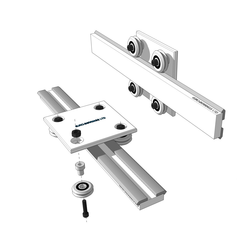
The Carriage and Bearings
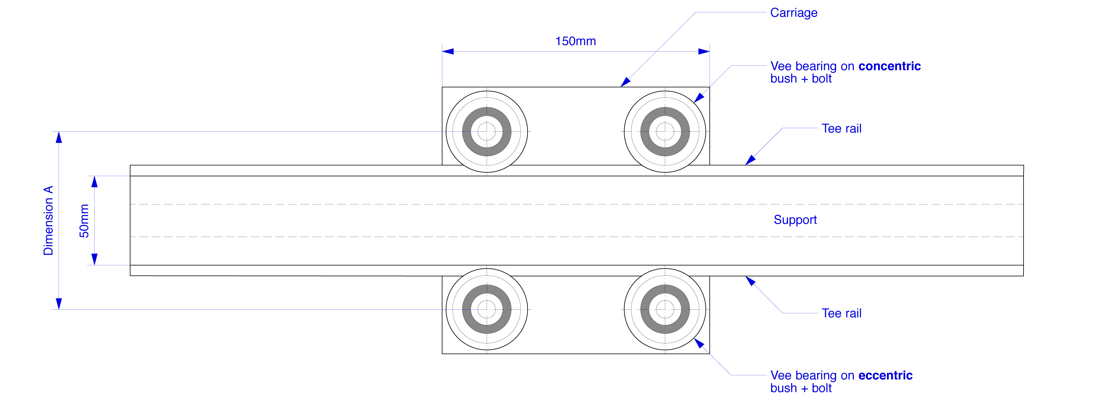
In this example we are making a carriage 150mm x 150mm with 4 no. W3X bearings. So again, select the material, steel or aluminium, for the carriage. The hole centre positions for the bearings (dimension “A” on the drawing) can be calculated as:
A = Width of support + 2 x TE + 2 x A1
The value for dimension TE can be found here http://www.euro-bearings.com/veerails.htm (TE in this case is 6.35mm).
And the value for dimension A1 can be found here http://www.euro-bearings.com/veesizes.htm (A1 in this case is 19.05mm).
NOTE: Dimension TE is the offset of tip of Vee rail from the support material. A1 is the dimension from centre of bearing to bottom of Vee. In our example this is 50 + (2x 6.35) + ( 2 x 19.05) = hole centres 100.8mm.
The eccentric bush MB3X allows 1.07mm of lateral adjustment.
Drill the holes through the carriage plate at 100.8mm centres (in this case 8.2mm diameter clearance holes for the M8 bolts we will use to secure the bearings).
Insert the concentric bushes into 2 bearings and insert the eccentric bushes into 2 bearings. Firmly secure the concentric bushed bearings to one side of the carriage plate and tighten. Loosely assemble the eccentric bushed bearings to the carriage plate and slide the carriage onto the T-rails. Now adjust the eccentric bushed bearings by feel (or feeler gauge) to achieve the pre-load required. Slide the carriage back & forth to ensure there are no pinch points. It is recommended to use hex cap head bolts and nyloc nuts through each bearing bush.
IMPORTANT: Make sure the outer ring of the bearing is turning on the inner ring of the bearing and NOT on the bush. The bearing should be an interference fit onto the bush.