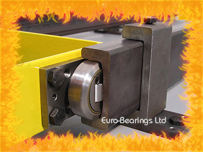
Combined Roller Bearings & Mating Steel Profiles are one of the most versatile linear motion systems. Originally used on forklift trucks, the bearings are designed to carry both the axial and radial loads in one unit. The bearings and rails can be used horizontally and vertically, and can also be arranged telescopically to allow for full extension.
The main advantage of Combined Roller Bearings over other track rolling systems is that the smaller axial rollers contact the web of the profiled rails. This helps to keep the system running parallel and consequently prevents it from jamming.
The bearings can be supplied pre-welded to a mounting plate and then simply bolted onto the carriage or they can be welded directly to the structure for a more compact configuration.
Here are some of the possible arrangements:
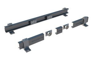 |  | 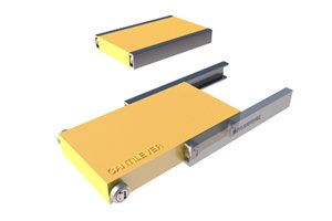 |
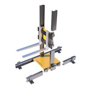
| Simple Horizontal System | Combined Horizontal / Vertical | Horizontal Cantilever |
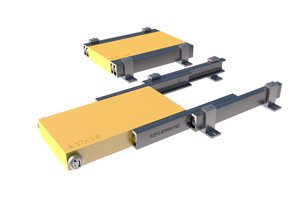 | 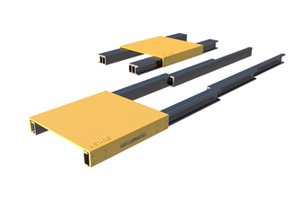 | 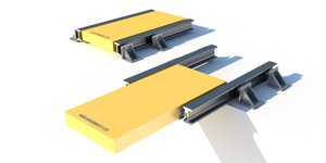 |
| 2 Stage Telescopic System | 3 Stage Telescopic System | I Beam Cantilevered System |
Click on an image for further information.
With good resistance to dirt and heat, Combined Roller Bearings can be used in many industrial applications: from packaging machines to furnace loaders, brick makers to offshore pipe and cable laying devices, to name just a few.
If you have a heavy duty linear motion application, please contact our technical sales team for help and advice.
Details on how to select the correct size of bearing can be found here.